This project started out with the idea of unveiling a new race track for our summer robotics program. This project is one part of several projects that will be part of this race track overhaul.
Here is what I sketched up so you can see the simple beginnings of what has lead me to long hours of building, soldering, desoldering, soldering again, building prototypes, problem solving, coding, learning to stay patient and keep trying and more. The process of developing a working LED Lap Timer is designed to gauge the speed of various robots, car, and vehicles.


I started with the idea based on some ideas shared on the Cannybots forum. I have some Cannybots in my Makerspace and currently developing some summer camps and after school opportunities.
The forum shared the following information to get started
Parts List
- 5x LED i2c Backpack
- Data sheet for LED i2c Backpack and Matrix
- 6x Jumper Wire – 0.1″, 4-PIN, 12″
- Laser module
- Light Sensor
- 1x Arduino
- 20 Male headers pins, for i2c connector block
- 6x AA rechargable batters
- 1x Battery Holder for 6 AA Batteries
- 9v connector clip (tinned ends)
- Mini Breadboard
- Wire for connecting sensor, laser and wiring harness to the breadboard
- Black electrical tape to hold wiring harness pin headers together
- 3D printed or laser cut structure(I made a prototype out of cardboard that worked pretty good. 3D printer is not mandatory, but if you have one we have the STL listed below.
Power
~6v to the Arduino VIN pin and the LED backpack, using the breadboard
Display
The LED backpacks have uniqie i2c addresses set (70-75, we did not use 72. There is no particular reason besides not wanting to desolder and solder again for the fourth time) using solder on the back.
Any backpack compatible with the Adafruit library should be ok, check voltages!
Wiring harness
The headers pins are split into 6 pin segments and then every pin on every individual segment is joined together using solder. The harness connects the +V, GND, SDA & SDC from the Arduino to all the LED backpacks in parallel.

- Connect SCL (yellow) to the I2C clock – on Arduino UNO thats Analog #5, on the Leonardo its Digital #3, on the Mega its digital #21
- Connect SDA (green) to the I2C data – on Arduino UNO thats Analog #4, on the Leonardo its Digital #2, on the Mega its digital #20
- Connect GND (black) to common ground (i.e. battery and Arduino)
- Connect VCC+ (red) to power – 5V is best but 3V also seems to work for 3V micro controllers.
The light blue/cyan blobs represent where solder needs to be applied to bridge the connections in order to set the I2C address, this is where the order is important, if this is back to front the numbers of the laptime will be displayed in reverse order.
Arduino
Please install the 2 Adafruit libraries required by following the instructions here.
The sketch can be found here.
It has some wiring information and also information relating to which pins, on different types of Arduino’s, map to interrupt numbers in software.
The Arduino Sketch uses an interrupt handler triggered by pin voltage change to detect the break in the laser beam.
Step 1: Gathering Pieces and Solder LED Matrix to Backpack
I went through and made sure I had everything I needed.

Once I knew I had what I needed to started with the LED 8×8 matrix and backpacks. I have never used LED and am a newbie maker so I was excited to work on these. Basically, stay patient as you try to line up all the pins to fit the holes. Once they are all lined up you can start to solder them all in. I won’t give a solder lesson, but take your time to make sure you don’t develop solder bridges. Nice and easy is the key. However, make sure you install the matrix on correctly so you can avoid my errors and be able to skip step 1.2. I share step 1.2 in case you make the mistake.
In the video showcasing my journey I did solder right away. If I were to do this project again I would solder the LED matrix to the backpack first.
Step 1.2: Fixing Mistake
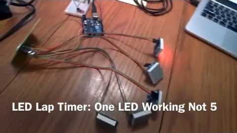
Midway through the second big day of work I became stuck. Only one LED was working, but not the other four.
What I learned is that it is important to study schematics, read data sheets, and do some research on the parts. Like most of us I dove right in and tried to figure it out as I went along. Had I taken time to read some materials it would have saved me a ton of time and headache.
Basically, I soldered the LED i2c Backpack on upside down. After many hours of trying different things(in which I did discover a few other errors so it was not all in waste) I realized this simple mistake when I started reading all the links on Adafruit website. To be honest this was not easy to find so here it is as a reference on how to properly solder and install the 8×8 LED Matrix to the backpack.
Here is how it should look!

I was somewhat lucky in that in reality only three had to be desoldered, removed, and soldered again. Adafruit claims the following:

They are pretty accurate. I escaped with minimum damage and to do it again I would just buy new parts. It was a great learning experience.
If you happen to mess it up after all of this here is what I did to salvage the parts and still make it all work.
Step 2: Jumper Wire and Male Pins
Take the six jumper wires and grab the male pins that are found in the backpack kits. You can also use the extra pins from the 20 pin male header piece as well.

Take the jumper wire and connect four male heads into the wire. Do this for all six jumper wires.

Make sure you have good connections.

Once you have them all connected to the jumper wires, then it is time to place into the SCL, SDA, GRD, and VCC spots on the backpack. Make sure you line up the same wire colors for each spot on all five LED.

When you have double checked to make sure they are all lined up correctly go ahead and solder.
Step 3: PCB Board and Jumper Wires
Because we need five wires along with power we cannot use a breadboard. There are not enough spots to wire everything together. We will use a basic PCB board to solder all the jumper wires along with the power cables to connect to the Arduino.

Here is the PCB that I used. I will clean this up and trim it down when it comes time to clean the whole project up, but for now it does not matter.

I soldered five rows of four male headed pins to the board. The six row are just wires from my Arduino kit. I soldered one side to the PCB board. I am sure there are other ways, but this works.

On the backside you have to solder bridge the wires together. It gets a bit messy, but it does work. Solder the same color wires together(six in total). I took a mini saw and cut between each row to make sure there were no cross connections. I know it is not pretty, but it does the job. This took some patience.
A B C D
0 0 0 0 LED 1 Jumper cable
0 0 0 0 LED 2 Jumper cable
| | | |
0 0 0 0 LED 3 Jumper cable
| | | |
0 0 0 0 LED 4 Jumper cable
| | | |
0 0 0 0 LED 5 Jumper cable
| | | |
0 0 0 0 To power and the i2c pins on Ardio


Step 4: Connect to Arduino
It is now time to connect to the Arduino to see if we are good to go. I won’t lie this step was where I had to go back and troubleshoot so this is a good checkpoint before finalizing the build.

SCL(Green) goes to Arduino A5
SDA(Yellow) goes to Arduino A4
GND(Orange) goes to Arduino GND
VCC(red) goes to Arduino 5V

Step 5: Wire the Sensor
Step 6: 3D Print Frame
Step 7: Install
Contributions
This project would not be possible without the following people. It started with the two following people who are rockstars. They have developed Cannybots and spent a lot of time via email helping me troubleshoot and make things happen.
Wayne Keenan
Anish Mampetta
Also, the members of the Arduino Google+ community for sharing ideas as well.
Leave a Reply